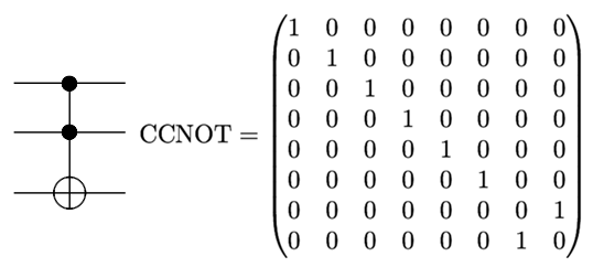
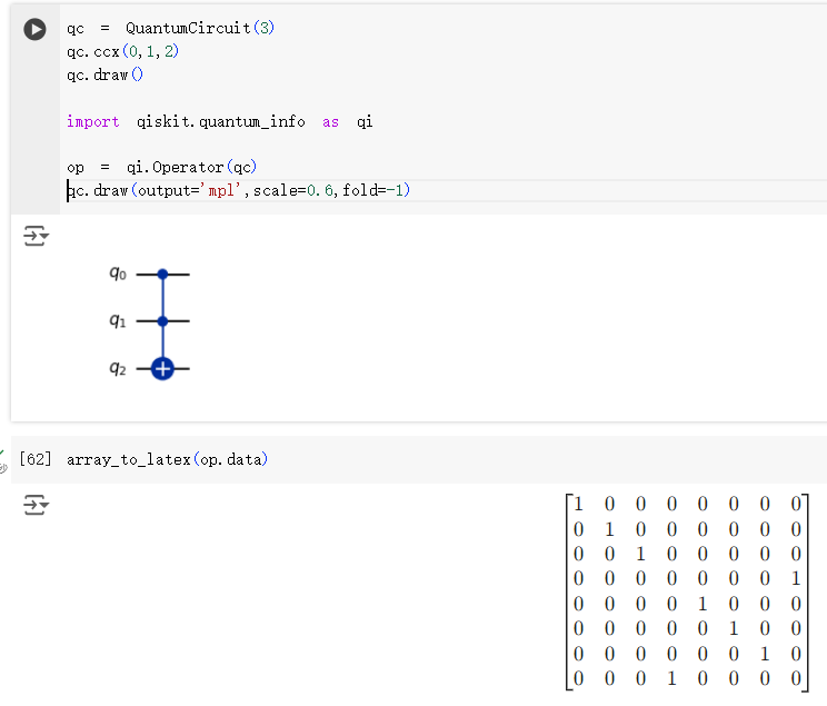
This is because Qiskit uses tensor ordering convention different from what is used in most quantum computing textbooks.
According to a recent preprint from Qiskit team:
When interpreting circuits, a convention must be
picked for the ordering of qubits in a register, arguments
of all instructions, and of instructions themselves. For
example it is common that instructions in a circuit are
ordered from left to right (i.e. temporal ordering), which
is the opposite of how gate matrices are multiplied in the
circuit.
Throughout Qiskit, tensor products are ordered as $Q_2 \otimes Q_1 \otimes Q_0$. For example, the Pauli $ZX$ means $Z_1X_0$. In this convention, the computational basis can
be conveniently represented as $|000⟩=|0⟩, |001⟩=|1⟩, |010⟩=|2⟩, |011⟩=|3⟩$, etc.
This leads to more natural representations of reversible circuits too, as numbers are encoded in qubit registers in the same way as they would be in classical registers. Note that this is merely a convention, which may be natural for some tasks but not others. For example, the qubit arguments to a $CX$
instruction are ordered as $Q_0$=control and $Q_1$=target,
This leads to a unitary of $CX=
\left( {\begin{array}{*{20}{c}} 1&0&0&0 \\ 0&0&0&1 \\ 0&0&1&0 \\ 0&1&0&0 \end{array}} \right)$
, which may be different to some textbook definitions of the gate.
QuantumCircuit class contains the method reverse_bits() which can be used to reverse the order of wires. Similarly, Operator class contains reverse_qargs() method. You can use any one of them to get the expected matrix:
op = Operator(qc.reverse_bits())
array_to_latex(op)
Or,
op = Operator(qc)
array_to_latex(op.reverse_qargs())


