1
$\begingroup$

I am currently studying Qiskit.

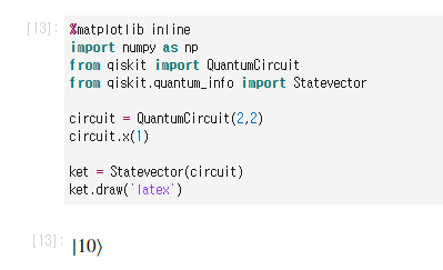
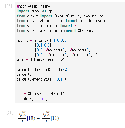
I don't understand the two pictures below while studying.

enter image description here

enter image description here

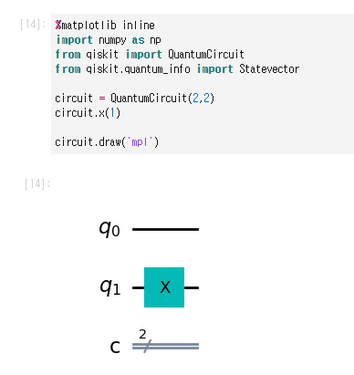
When I apply circuit.x(1), the X gate should be applied to the second qubit, resulting in the state |01>. However, I don't understand why I'm getting |10> instead. What could be the issue?

enter image description here

I posted a question and upon reflection, it seems that in Qiskit, the statevector ordering is such that when denoting the first qubit as q1 and the second qubit as q2, the output is in the form |q2q1>. To test this, I used an arbitrary controlled unitary gate.

If the ordering is opposite to most textbooks, and assuming circuit.x(1) flips the second qubit to 1, independent of ordering, the controlled unitary gate shouldn't operate because the state |q2q1> would be |10>. However, it seems to operate in this case. Is it correct to assume in Qiskit that if the leftmost bit of the statevector is 1, the controlled U gate operates, regardless of which qubit had the x gate applied?

$\endgroup$

1 Answer 1

2
$\begingroup$

Qiskit uses this order for qubits: $|q_N q_{N-1} ... q_1 q_0 \rangle$. You already figured it out. I had the same problem when I started learning Qiskit. I had to change all the circuits in the book (Nielsen and Chuang) when implementing them on Qiskit, like those for producing Bell states.

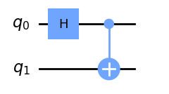
Circuit for create Bell States

In the aboce circuit (pag 26, Nielsen and Chuang), input $|10 \rangle$ doesn't produce the expected output $|\beta_{10}\rangle=\frac{\sqrt{2}}{2} |00\rangle- \frac{\sqrt{2}}{2} |11\rangle$

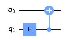
You will need to use this lightly modified circuit:

enter image description here

$\endgroup$

Your Answer

By clicking “Post Your Answer”, you agree to our terms of service and acknowledge you have read our privacy policy.

Not the answer you're looking for? Browse other questions tagged or ask your own question.