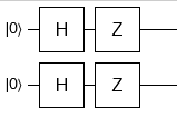
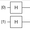
One way to do that using Qiskit is to write down the unitary matrix which transforms input states to output states then using QuantumCircuit.unitary()[1] method.
The unitary should be $4\times4$. First column corresponds to the output of the $|00\rangle$ state. Second column corresponds to the output of the $|01\rangle$ state. And so on.
Try to do it yourself then verify the result is:
\begin{bmatrix}
0.5 & 0.5 & 0.5 & 0.5
\\ -0.5 & -0.5 & 0.5 & 0.5
\\ -0.5 & 0.5 & -0.5 & 0.5
\\ 0.5 & -0.5 & -0.5 & 0.5
\\
\end{bmatrix}
Now create the circuit:
matrix = [
    [ 0.5,  0.5,  0.5, 0.5],
    [-0.5, -0.5,  0.5, 0.5],
    [-0.5,  0.5, -0.5, 0.5],
    [ 0.5, -0.5, -0.5, 0.5],
]

# Create the circuit:
circ = QuantumCircuit(2)
circ.unitary(matrix, [0, 1])

# Draw it:
circ.decompose().draw('mpl')
To verify the end result you can simulate it using StatevectorSimulator[2]. However, for small circuits like the one we have here, there is a simpler way:
from qiskit.quantum_info import Statevector
from qiskit.quantum_info.operators import Operator

Statevector.from_label('00').evolve(circ).draw('latex')
You can put 01, 10, or 11 instead of 00 to check the result.


