A full adder is usually depicted like this, with 1-bit inputs, sum, and carry:
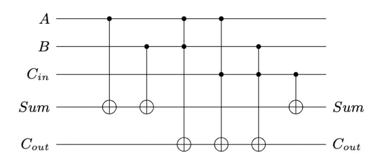
A simple quantum circuit for the corresponding truth table could be drawn like this:
In my own code base, this translates into this code:
  psi = ops.Cnot(0, 3)(psi, 0)
  psi = ops.Cnot(1, 3)(psi, 1)
  psi = ops.ControlledU(0, 1, ops.Cnot(1, 4))(psi, 0)
  psi = ops.ControlledU(0, 2, ops.Cnot(2, 4))(psi, 0)
  psi = ops.ControlledU(1, 2, ops.Cnot(2, 4))(psi, 1)
  psi = ops.Cnot(2, 3)(psi, 2)
  return psi
This code applies the gates one after the other. So in order to obtain a single big matrix you have to multiply all the gates together in reverse order and properly pad them to 5 qubits, as in the following (assuming I didn't make a mistake here), where * denotes the Kronecker product and @ is matrix multiply:
  M = ((ops.Identity(2) * ops.Cnot(2, 3) * ops.Identity(1)) @
       (ops.Identity(1) * ops.ControlledU(1, 2, ops.Cnot(2, 4))) @
       (ops.ControlledU(0, 2, ops.Cnot(2, 4))) @
       (ops.ControlledU(0, 1, ops.Cnot(1, 4))) @
       (ops.Identity(1) * ops.Cnot(1, 3) * ops.Identity(1)) @
       (ops.Cnot(0, 3) * ops.Identity(1)) )
The resulting matrix is $2^5 \times 2^5$ and looks something like:
Operator for 5-qubit state space. Tensor:
[[1.+0.j 0.+0.j 0.+0.j ... 0.+0.j 0.+0.j 0.+0.j]
 [0.+0.j 1.+0.j 0.+0.j ... 0.+0.j 0.+0.j 0.+0.j]
 [0.+0.j 0.+0.j 1.+0.j ... 0.+0.j 0.+0.j 0.+0.j]
 ...
 [0.+0.j 0.+0.j 0.+0.j ... 0.+0.j 1.+0.j 0.+0.j]
 [0.+0.j 0.+0.j 0.+0.j ... 1.+0.j 0.+0.j 0.+0.j]
 [0.+0.j 0.+0.j 0.+0.j ... 0.+0.j 0.+0.j 0.+0.j]]
This should be relatively simple to achieve in other infrastructures, such as Qiskit. Hope this helps.


