33
$\begingroup$

I'm creating a gate for a project and need to test if it has the same results as the original circuit in a simulator, how do I build this gate on Qiskit? It's a 3 qubit gate, 8x8 matrix:

$$ \frac{1}{2} \begin{bmatrix} 1 & 0 & 1 & 0 & 0 & 1 & 0 & -1 \\ 0 & 1 & 0 & 1 & 1 & 0 & -1 & 0 \\ 0 & 1 & 0 & -1 & 1 & 0 & 1 & 0 \\ 1 & 0 & -1 & 0 & 0 & 1 & 0 & 1 \\ 1 & 0 & 1 & 0 & 0 & -1 & 0 & 1 \\ 0 & 1 & 0 & 1 & -1 & 0 & 1 & 0 \\ 0 & 1 & 0 & -1 & -1 & 0 & -1 & 0 \\ 1 & 0 & -1 & 0 & 0 & -1 & 0 & -1 \end{bmatrix} $$

$\endgroup$
4
  • $\begingroup$ Ideally you would do this by telling qiskit that you want the gate specified by this matrix. I'm not sure that feature exists yet, but I'm trying to find out. $\endgroup$ Commented Dec 18, 2018 at 10:55
  • $\begingroup$ @Nillmer Your original circuit needs this gate or you need to check if the circuit corresponds to this unitary? $\endgroup$
    – cnada
    Commented Dec 19, 2018 at 3:16
  • $\begingroup$ @cnada I need to check if the circuit corresponds to this unitary. $\endgroup$
    – Nillmer
    Commented Dec 19, 2018 at 11:45
  • $\begingroup$ @Nillmer See my answer and tell me if that would do the job. $\endgroup$
    – cnada
    Commented Dec 19, 2018 at 12:44

6 Answers 6

5
$\begingroup$

I don't think Qiskit has this simulation feature. You have to decompose it indeed.

However, there is another way to solve your problem. To check if a quantum circuit (that you can submit in Qiskit) corresponds to a unitary matrix, you can use the unitary_simulator backend.

# Run the quantum circuit on a unitary simulator backend
backend = Aer.get_backend('unitary_simulator')
job = execute(circ, backend)
result = job.result()
print(np.around(result.get_unitary(circ), 3))

This will print the unitary matrix that your circuit represents. And you can compare to yours.

$\endgroup$
0
29
$\begingroup$

You can build your gate with Operator and unitary function e.g:

from qiskit import QuantumCircuit, QuantumRegister
from qiskit.quantum_info.operators import Operator

controls = QuantumRegister(2)
circuit = QuantumCircuit(controls)

cx = Operator([
    [1, 0, 0, 0],
    [0, 0, 0, 1],
    [0, 0, 1, 0],
    [0, 1, 0, 0]
])
circuit.unitary(cx, [0, 1], label='cx')

Output:
         ┌──────────┐
q0_0: |0>┤0         ├
         │  unitary │
q0_1: |0>┤1         ├
         └──────────┘

This is identical to:

circuit.cx(controls[0], controls[1])

Output:

q0_0: |0>──■──
         ┌─┴─┐
q0_1: |0>┤ X ├
         └───┘

For more info look Qiskit tutorials: https://qiskit.org/documentation/tutorials/simulators/4_custom_gate_noise.html

$\endgroup$
1
  • $\begingroup$ Thank you! This explanation cleared up much confusion. $\endgroup$
    – user727041
    Commented Nov 29, 2019 at 22:57
9
$\begingroup$

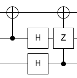
Here's the circuit for your specific case:

circuit

I made it manually, by entering the matrix into Quirk, diagonalizing the matrix by adding operations, then simplifying the operations. It's not too hard to do by hand when all the operations are Clifford as in this case.

$\endgroup$
5
  • $\begingroup$ That last column looks weird. I guess since CNOT and Z commute, it puts them on the same column regardless of whether looks like a CZ. Would prefer a diagram overlap check before it draws the circuit. $\endgroup$
    – AHusain
    Commented Dec 18, 2018 at 23:43
  • $\begingroup$ @AHusain It's a CZ and a CNOT, not a Z and a CNOT. The overlap is intentional and means "each of those operations is controlled by the control". $\endgroup$ Commented Dec 19, 2018 at 1:22
  • 1
    $\begingroup$ Ok. Would it overlap like that in the CNOT and Z case as well? Or would they separate? Ideally the diagram should not be ambiguous as to which lines connect where. $\endgroup$
    – AHusain
    Commented Dec 19, 2018 at 2:20
  • $\begingroup$ @AHusain If it was a Z gate it would have to be placed on a separate vertical column. Otherwise it would be ambiguous, as you note. $\endgroup$ Commented Dec 19, 2018 at 3:06
  • $\begingroup$ I would be extremely grateful if you could elaborate on the logic you use to build the circuit on quirk. I am in the same situation i.e. I need to find the gate decomposition of a specific matrix. Instead of creating a redundant question, I figured if you could briefly explain what logical step to use to achieve that result in quirk it would be of help. $\endgroup$
    – Enrico
    Commented Jul 24, 2020 at 8:05
4
$\begingroup$

Qubiter uses a CSD compiler for a Unitary matrix to a sequence of elementary operations tranformation

One setback is that qubiter needs extra packages so installing could be troublesome.

$\endgroup$
3
$\begingroup$

You can't directly build a gate from arbitrary matrices because custom gates need to be implemented using the build-in gates.

You have to decompose your matrix to known gates.

For a random two-qubit gate, there is two_qubit_kak:

two_qubit_kak (unitary_matrix, verify_gate_sequence=False)

Decompose a two-qubit gate over CNOT + SU(2) using the KAK decomposition.

Based on MATLAB implementation by David Gosset.

Computes a sequence of 10 single and two qubit gates, including 3 CNOTs, which multiply to U, including global phase. Uses Vatan and Williams optimal two-qubit circuit (quant-ph/0308006v3). The decomposition algorithm which achieves this is explained well in Drury and Love, 0806.4015.

$\endgroup$
1
  • $\begingroup$ The link is not found $\endgroup$
    – hola
    Commented Apr 16, 2019 at 17:50
3
$\begingroup$

Cirq since 0.10 (you can install it using pip install cirq --pre) has a function to decompose an arbitrary three qubit unitary cirq.three_qubit_matrix_to_operations. This, combined with cirq.qasm can generate 1 and 2 qubit gates in OpenQASM 2.0. Note that this is a pretty verbose decomposition (but at most 20 CZs), as it is based on generic linear algebra decompositions.

import numpy as np 

qs = cirq.LineQubit.range(3)

print(cirq.qasm(cirq.Circuit(cirq.three_qubit_matrix_to_operations(qs[0], qs[1], qs[2], 1/2*np.array([
[1,0,0,1,1,0,0,1],
[0,1,1,0,0,1,1,0],
[1,0,0,-1,1,0,0,-1],
[0,1,-1,0,0,1,-1,0],
[0,1,1,0,0,-1,-1,0],
[1,0,0,1,-1,0,0,-1],
[0,-1,1,0,0,1,-1,0],
[-1,0,0,1,1,0,0,-1],
])))))

Which will output:

// Generated from Cirq v0.10.0.dev

OPENQASM 2.0;
include "qelib1.inc";


// Qubits: [0, 1, 2]
qreg q[3];


u2(pi*0.011229858, pi*-0.011229858) q[1];
u3(pi*-0.2503051573, pi*-0.4802949152, pi*0.4802949152) q[2];
rz(pi*-0.5) q[0];
cz q[1],q[2];
u3(pi*-0.4860708536, pi*0.511229858, pi*-0.511229858) q[1];
cz q[1],q[2];
u3(pi*-0.7496948427, pi*0.0057759385, pi*-0.0057759385) q[2];
u2(pi*0.011229858, pi*-0.011229858) q[1];
rz(pi*-0.5254810233) q[2];
rz(pi*0.9972453689) q[1];
cx q[1],q[0];
rz(pi*0.5) q[0];
cx q[2],q[0];
rz(pi*-0.5) q[0];
cx q[1],q[0];
rz(pi*-0.5) q[0];
u2(pi*-1.2086038449, pi*1.2086038449) q[1];
cx q[2],q[0];
u3(pi*-0.4803325646, pi*-0.0197050848, pi*0.0197050848) q[2];
ry(pi*0.5) q[0];
cz q[1],q[2];
rz(pi*-0.5) q[0];
u3(pi*-0.2506091478, pi*1.2913961551, pi*-1.2913961551) q[1];
cz q[1],q[2];
u3(pi*-0.5196674354, pi*-0.2703142327, pi*0.2703142327) q[2];
u2(pi*-1.2086038449, pi*1.2086038449) q[1];
rz(pi*-0.7099806825) q[2];
rz(pi*0.9369127746) q[1];
u2(0, 0) q[1];
u3(pi*-0.2870621217, pi*1.0, pi*-1.0) q[2];
cz q[1],q[2];
u3(pi*-0.2129378783, pi*1.0, pi*-1.0) q[2];
u2(pi*-1.0, pi*1.0) q[1];
cz q[1],q[2];
u2(pi*-1.0, pi*1.0) q[1];
u3(pi*-1.0, pi*1.25, pi*-1.25) q[2];
rz(pi*-0.5) q[1];
cx q[1],q[0];
cx q[2],q[0];
rz(pi*0.5) q[0];
cx q[1],q[0];
cx q[2],q[0];
u2(pi*0.25, pi*-0.25) q[1];
u2(pi*-0.75, pi*0.75) q[2];
cz q[1],q[2];
u3(pi*-0.2129378783, pi*1.25, pi*-1.25) q[2];
u3(pi*-0.2129378783, pi*1.25, pi*-1.25) q[1];
cz q[1],q[2];
u3(pi*-0.25, pi*-0.25, pi*0.25) q[2];
u2(pi*-0.75, pi*0.75) q[1];
rz(pi*-1.25) q[2];
$\endgroup$

Your Answer

By clicking “Post Your Answer”, you agree to our terms of service and acknowledge you have read our privacy policy.

Not the answer you're looking for? Browse other questions tagged or ask your own question.