Context:
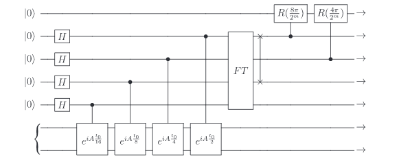
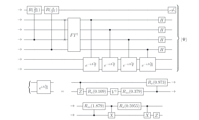
On the 5th page of the paper Quantum circuit design for solving linear systems of equations (Cao et al, 2012) there's this circuit:
Schematic:
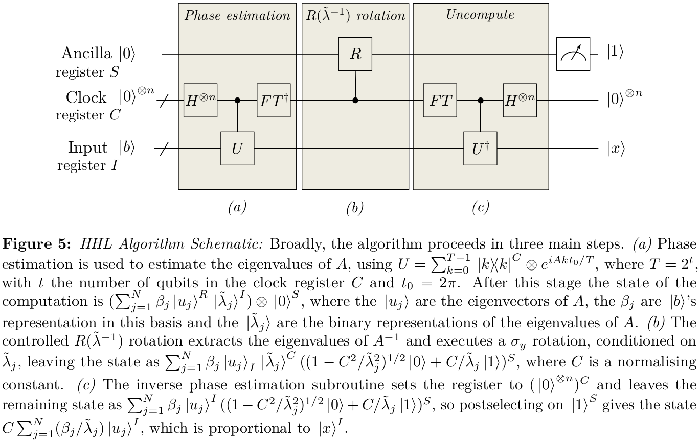
A brief schematic of what's actually happening in the circuit is:
Question:
Cao et al.'s circuit (in Figure 4) is specifically made for the matrix:
$$A = \frac{1}{4} \left(\begin{matrix} 15 & 9 & 5 & -3 \\ 9 & 15 & 3 & -5 \\ 5 & 3 & 15 & -9 \\ -3 & -5 & -9 & 15 \end{matrix}\right)$$
whose eigenvalues are $\lambda_1 = 2^{1-1}=1,\lambda_2 = 2^{2-1}=2,\lambda_3 = 2^{3-1}=4$ and $\lambda_4 = 2^{4-1} = 8$ and corresponding eigenvectors are $|u_i\rangle = \frac{1}{2}\sum_{j=1}^{4}(-1)^{\delta_{ij}}|j\rangle^C$. In this case since there are $4$ qubits in the clock register, the $4$ eigenvalues can be represented as states of the clock register itself (no approximation involved) i.e. as $|0001\rangle$ (binary representation of $1$), $|0010\rangle$ (binary representation of $2$), $|0100\rangle$ (binary representation of $4$) and $|1000\rangle$ (binary representation of $8$).
After the first Quantum phase estimation step, the circuit's (in Fig. 4) state is
$$|0\rangle_{\text{ancilla}} \otimes \sum_{j=1}^{j=4} \beta_j |\lambda_j\rangle |u_j\rangle$$
Everything is fine till here. However, after this, to produce the state
$$\sum_{j=1}^{j=4} \beta_j |u_j\rangle_I |\lambda_j\rangle^C ((1-C^2/\lambda_j^2)^{1/2}|0\rangle + C/\lambda_j|1\rangle)$$
it seems necessary to get to the state $$\sum_{j=1}^{j=4} \beta_j |u_j\rangle_I |\frac{2^{3}}{\lambda_j}\rangle^C\otimes |0\rangle_{\text{ancilla}}$$
That is, the following mappings seem necessary in the $R(\lambda^{-1})$ rotation step:
$$|0001\rangle \mapsto |1000\rangle, |0010\rangle \mapsto |0100\rangle, |0100\rangle \mapsto |0010\rangle \ \& \ |1000\rangle \mapsto |0001\rangle$$
which implies that the middle two qubits in the clock register need to be swapped as well as the two end qubits.
But, in the circuit diagram they seem to be swapping the first and third qubit in the clock register! That doesn't seem reasonable to me. In the paper (Cao et al.) claim that the transformation they're doing using their SWAP gate is
$$\sum_{j=1}^{j=4} \beta_j |u_j\rangle_I |\lambda_j\rangle^C\otimes |0\rangle_{\text{ancilla}} \mapsto \sum_{j=1}^{j=4} \beta_j |u_j\rangle_I |\frac{2^{4}}{\lambda_j}\rangle^C\otimes |0\rangle_{\text{ancilla}}$$
According to their scheme, $|1000\rangle \to |0010\rangle$ (see the third page). This scheme doesn't make sense to me because the state $|0001\rangle$ (representing the eigenvalue $1$) would have to be transformed to $|2^4/1\rangle$. But the decimal representation of $16$ would be $|10000\rangle$ which is a 5-qubit state! However, our clock register has only $4$ qubits in total.
So, basically I think that their SWAP gates are wrong. The SWAPs should actually have been applied between the middle qubits and the two end qubits. Could someone verify?
Supplementary question:
This is not a compulsory part of the question. Answers addressing only the previous question are also welcome.
@Nelimee wrote a program (4x4_system.py in HHL) in QISKit to simulate the circuit (Figure 4) in Cao et al's paper. Strangely, his program works only if the SWAP gate is applied between the middle two qubits but not in between the two end qubits.
The output of his program is as follows:
<class 'numpy.ndarray'>
Exact solution: [-1  7 11 13]
Experimental solution: [-0.84245754+0.j  6.96035067+0.j 10.99804383+0.j 13.03406367+0.j]
Error in found solution: 0.16599956439346453
That is, in his program only the mapping $|0100\rangle \mapsto |0010\rangle$ takes place in the clock register in the $R(\lambda^{-1})$ step. There's no mapping $|1000\rangle \mapsto |0001\rangle$ taking place.
Just in case anyone figures out why this is happening please let me know in the comments (or in an answer).


