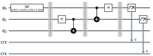
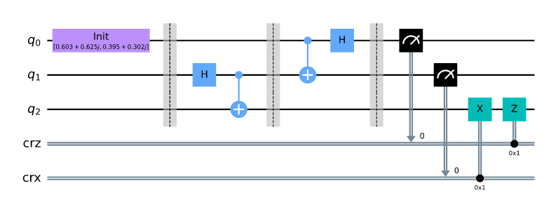
To extract the final state, $|\psi \rangle_{final}$, before the measurement step, which can be represented by the circuit:

You can do:
from qiskit import QuantumRegister, ClassicalRegister, QuantumCircuit
from qiskit import IBMQ, Aer, execute
import numpy as np

qreg_q = QuantumRegister(3, 'q')
circuit = QuantumCircuit(qreg_q)
vector = [0.603 + 0.625j,0.395 + 0.302j]
initial_state = vector/np.linalg.norm(vector)
circuit.initialize(initial_state, 0)
circuit.barrier(range(3))
circuit.h(qreg_q[1])
circuit.cx(qreg_q[1], qreg_q[2])
circuit.barrier(range(3))
circuit.cx(qreg_q[0], qreg_q[1])
circuit.h(qreg_q[0])
circuit.barrier(qreg_q[0], qreg_q[1], qreg_q[2])
backend = Aer.get_backend("statevector_simulator")
result = execute(circuit, backend=backend, shots=1).result()
print('Final State Vector:\n', result.get_statevector() )
Which will output the final state $|\psi\rangle_{final}$ as:
Final State Vector:
 [ 0.30127969+0.31227166j  0.30127969+0.31227166j  0.19735569+0.15088966j
 -0.19735569-0.15088966j  0.19735569+0.15088966j -0.19735569-0.15088966j
  0.30127969+0.31227166j  0.30127969+0.31227166j]
Now, if you want to extract each individual counts result from an experiment, then you first need to add in the measure like you have on the circuit in your question, then change the backend option to qasm_simulator (shot based simulator instead of exact matrix manipulation). Then execute your circuit and extract the count at each shot through specifying the memory to be True.
qreg_q = QuantumRegister(3, 'q')
creg_result1 = ClassicalRegister(1, 'crz')
creg_result2 = ClassicalRegister(1, 'crx')
circuit = QuantumCircuit(qreg_q, creg_result1, creg_result2)
vector = [0.603 + 0.625j,0.395 + 0.302j]
initial_state = vector/np.linalg.norm(vector)
circuit.initialize(initial_state, 0)
circuit.barrier(range(3))

circuit.h(qreg_q[1])
circuit.cx(qreg_q[1], qreg_q[2])
circuit.barrier(range(3))
circuit.cx(qreg_q[0], qreg_q[1])
circuit.h(qreg_q[0])
circuit.barrier(qreg_q[0], qreg_q[1], qreg_q[2])
circuit.measure(qreg_q[0], creg_result1[0])
circuit.measure(qreg_q[1], creg_result2[0])
print(circuit)

backend = Aer.get_backend("qasm_simulator")
job = execute(circuit, backend=backend, shots=10, memory=True)
print('result for each shot:', job.result().get_memory() )
output is:
result for each shot: ['1 0', '0 0', '1 0', '1 0', '0 1', '1 1', '1 1', '0 0', '0 1', '1 0']


