The following answer to this question was given by Dmitrii Maslov in a private conversation.
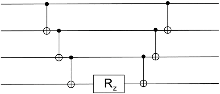
An improvement to the approach described in the original post can be made by noticing that the middle block of the circuit, containing two $CNOT$s and the $R_z$ rotation, is equivalent to the following circuit (which, in turn, is equivalent, up to a phase, to $\{Z_0^\alpha;Z_1^\alpha;CZ_{0,1}^{-2\alpha}\}$):
 ──■─────────────■──       ┌───────┐┌─────────┐          ┌─────────┐┌────────┐┌──────────┐
 ┌─┴─┐┌───────┐┌─┴─┐   =   ┤ RZ(α) ├┤ RY(π/2) ├──────────┤0        ├┤ RX(-3) ├┤ RY(-π/2) ├─────────
 ┤ X ├┤ RZ(α) ├┤ X ├       ├───────┤├─────────┴┐┌───────┐│  RXX(α) │├────────┤├──────────┤┌───────┐
 └───┘└───────┘└───┘       ┤ RZ(α) ├┤ RY(-π/2) ├┤ RZ(π) ├┤1        ├┤ RX(-3) ├┤ RY(-π/2) ├┤ RZ(π) ├
                           └───────┘└──────────┘└───────┘└─────────┘└────────┘└──────────┘└───────┘
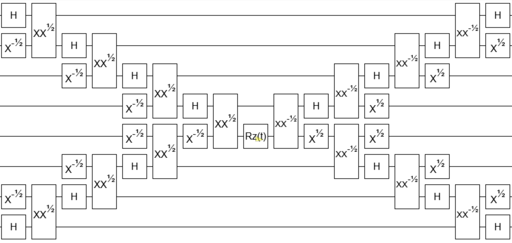
The advantage of this method is not not only in that it reduces the number of $XX$ gates by one. While all the $XX$ gates on the side have to be applied with the phase corresponding to the maximum entanglement (in order to reproduce $CNOT$s), the construction above only produces maximum entanglement in the worst case scenario.
NOTE: IN THE CIRCUIT ABOVE, I USED QISKIT CONVENTION FOR THE $XX$ GATE, I.E. MAXIMUM ENTANGLEMENT AT $\pi/2$. A MORE COMMON NOTATION IS HAVING MAXIMUM ENTANGLEMENT AT $\pi/4$, WHICH WOULD RESULT IN HAVING RXX(2α) IN THE MIDDLE.


