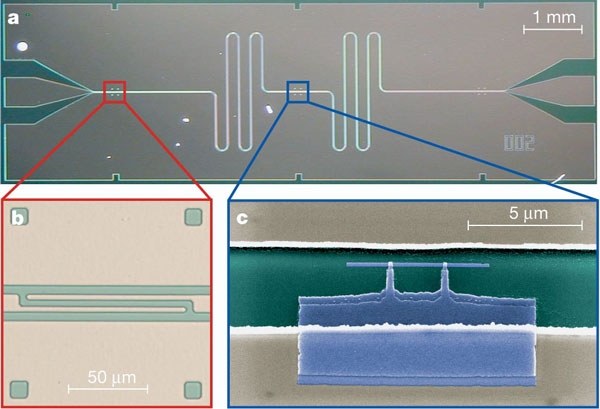
In scientific literature, one typically describes Cooper pair boxes as a small superconducting island coupled to a superconducting reservoir (say, a large ground plane of superconducting metal, or a large piece in any case) via a Josephson junction. This is for example illustrated in panel c below, taken from here
The main innovation of the transmon over the Cooper pair box was (if I am not mistaken) to shunt the island with a large capacitance, so as to decrease the sensitivity to charge. One can do this while maintaining the geometry of having an island and a large reservoir; see for example figure 1a of Anharmonicity of a Gatemon Qubit with a Few-Mode Josephson Junction by Kringhoj et al. (2017), where their Josephson junction (in this case an SNS junction made from a nanowire) shunts a T shaped island to the ground plane, the reservoir in this case. The large capacitance here is to ground. I apologise for using an exotic transmon here, I couldn't find a nice picture of a standard one; Studying Light-Harvesting Models with Superconducting Circuits by Potocnik et al. (2017) has grounded $\require{\mhchem}\ce{AlOx}$ transmons in figure 1b, but the level of zoom is a little low.
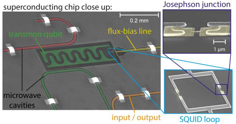
But something that I often see in modern transmon designs is that it is not a shunted island coupled to a reservoir; it is instead two coupled islands; take this figure from here. The capacitance here is between the two plates themselves.
Optically and intuitively, I would say that this is a rather different device; instead of having a small, isolated (up to Josephson coupling) island coupled to a large reservoir with a very large number of charges (which might even be grounded), one now has two such small, isolated islands with a small number of charges, galvanically isolated from the rest of the circuit. Moreover, the capacitance is now not to ground, but between the islands.
Now, I know that the Hamiltonian of these systems does not care about this difference; what matters is the number of Cooper pairs which have tunnelled across the junction, not the actual number of charges on the island(s). What my question is, is how in practice these devices do differ; why would one make their transmon in one way or the other? What constraints/considerations/findings have led modern designs to favour the two island version (if this is even true)? Do they have a better life and or coherence times, and if so, why? I've been trying to find literature that talks about the distinction between the two, but I have been unsuccessful.
Note: This has been cross posted on Physics SE.


