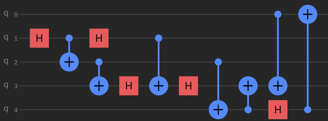
First of all, note that if you want to know the action of a quantum circuit of a given quantum state, you essentially have two options:
- Writing done the matrix representation of this circuit
- Feeding the state you're interested through the circuit to get the outcome
You simply have to pick the option that is faster. In this answer, I will describe the first one, since it will then allow to know the outcome for any bell State you feed your circuit with, and to make some recalls about the matrix representation of a circuit.
First of all, you have to take extra care when working with Qiskit to the qubit ordering. Contrarily to most textbooks, Qiskit orders qubits in little-endian, which means that the input state is represented as:
$$\left|q_4q_3q_2q_1q_0\right\rangle.$$
For instance, if you were to use the Bell state your provided in your question along with the GHZ state, the input state of your circuit would be:
$$\frac12\left(|00001\rangle+|00010\rangle+|11101\rangle+|11110\rangle\right)$$
This notation is important to consider, since this affects the matrix representation of a circuit. For instance, if we consider a two-qubits circuit, a CNOT gate on the second wire controlled by the first one is usually represented as:
$$\begin{pmatrix}1&0&0&0\\0&1&0&0\\0&0&0&1\\0&0&1&0\end{pmatrix}$$
while it is represented as, using Qiskit's notation:
$$\begin{pmatrix}1&0&0&0\\0&0&0&1\\0&0&1&0\\0&1&0&0\end{pmatrix}$$
Note that in both cases, the matrix representation has a nice property: it directly gives the result of this matrix applied on a basis state. For instance, if we consider the following gate:
$$\begin{matrix}\begin{pmatrix}\frac{1}{\sqrt{2}}&0&\frac{1}{\sqrt{2}}&0\\0&\frac{1}{\sqrt{2}}&0&\frac{1}{\sqrt{2}}\\0&\frac{1}{\sqrt{2}}&0&-\frac{1}{\sqrt{2}}\\\frac{1}{\sqrt{2}}&0&-\frac{1}{\sqrt{2}}&0\end{pmatrix}\end{matrix}$$
For instance, the first column gives the result we would have for applying this gate on the $|00\rangle$ state, the second one on the $|01\rangle$ state, etc... On the $|00\rangle$ state, this would give the state $\frac{1}{\sqrt{2}}|00\rangle+\frac{1}{\sqrt{2}}|11\rangle$.
Finally, it is not possible to write a CNOT gate between two non-consecutive qubits as a tensor product of CNOT and identity gates. This explains why you can't manage to write for instance the last operation in such a form. What you would have to do is to define the $CNOT_{n,c,a}$ gate, where $n$ is the number of qubits in the system, $c$ is the qubit the $NOT$ is controlled by and $a$ is the qubit on which the $NOT$ is applied. In certain circumstances, you can express, as you did, this gate as a tensor product, like:
$$CNOT_{5,1,2}=I\otimes CNOT_{2,0,1}\otimes I\otimes I$$
But in general, you can't define every $CNOT_{n,c,a}$ gate using only a tensor product of $I$ gates and $CNOT_{2,0,1}$ gates.
What you have to do is thus to write down the associated matrix by computing what its action on the basis states is. Once you have done this for any gate, you just have to multiply these matrices together to get the matrix representation.
However, this process is quite tedious, and we can speed things up a bit. For this, we just have to know the effect of the whole circuit on the basis states. In your case, there are $2^5=32$ of them, but once again, we can speed things up by considering some facts about the circuit. For instance, note that the $q_1$ qubit is always mapped to the same qubit. Unfortunately, you still have a lot of states to compute, and you cannot treat each qubit independently as with $q_1$, you have to go thourgh every state, which can be quite tedious, but at least now you know the general way of computing such a matrix.
Since you have drawn the circuit using Qiskit, you can use Qiskit to give you the matrix representation of your circuit, as follows:
from qiskit.quantum_info import Operator
from qiskit.visualization import array_to_latex

circ = QuantumCircuit(5)
circ.h(1)
circ.cnot(1, 2)
circ.h(1)
circ.cnot(2, 3)
circ.h(3)
circ.cnot(1, 3)
circ.h(3)
circ.cnot(2, 4)
circ.cnot(4, 3)
circ.cnot(0, 3)
circ.h(4)
circ.cnot(4, 0)
array_to_latex(Operator(circ).data, max_size=32)
which gives you the desired matrix. Now, it's just the matter of reading out the columns and summing them accordingly, or performing matrix multiplication. For instance, using the state outlined above, the resulting state is given by:
gate = Operator(circ).data
state = np.zeros(32, dtype=float)
state[1] = .5
state[2] = .5
state[29] = .5
state[30] = .5
array_to_latex(gate @ state, max_size=32)
which gives us:
$$\begin{bmatrix}
0 & 0 & 0 & 0 & 0 & 0 & 0 & 0 & 0 & \tfrac{1}{\sqrt{8}} & 0 & \tfrac{1}{\sqrt{8}} & 0 & \tfrac{1}{\sqrt{8}} & 0 & \tfrac{1}{\sqrt{8}} & 0 & \tfrac{1}{\sqrt{8}} & 0 & \tfrac{1}{\sqrt{8}} & 0 & \tfrac{1}{\sqrt{8}} & 0 & \tfrac{1}{\sqrt{8}} & 0 & 0 & 0 & 0 & 0 & 0 & 0 & 0 \
\end{bmatrix}$$
We can see that all these amplitudes are equal to $\frac{1}{\sqrt{8}}$. We can easily retrieve what the associated states are using:
[bin(x)[2:].zfill(5) for x in np.where(gate @ state != 0)[0]]
which finally gives us the state:
$$\frac{1}{\sqrt{8}}(|01001\rangle + |01011\rangle + |01101\rangle+ |01111\rangle + |10001\rangle + |10011\rangle +|10101\rangle +
|10111\rangle)$$
which can be rewritten as:
$$\frac{1}{\sqrt{8}}(|01\rangle+|10\rangle)(|00\rangle+|01\rangle+|10\rangle+|11\rangle)|1\rangle=|\psi\rangle|+\rangle|1\rangle$$

